
Demystifying the dip coating process
Hard coating of ophthalmic lenses
For most of the ophthalmic laboratories, among the many steps for lens manufacturing, the most critical one is certainly the hard coating process. This is probably linked to the fact that it is a chemistry related process and not a purely mechanical one. Most laboratory managers have a good knowledge of optics, mechanics and IT, but little or no knowledge of chemistry. Besides, machine manufacturers share the same knowledge features as their customers. Most of them believe that there is a cleaning/rinsing operation before the dip coating of the lenses, but this is not really the case. Some others may know
that it is not really the case, but since they also sell consumables, including lacquers, their interest is to maximise the consumption of the chemicals in their machines. By François Breton

Actually, there are two parts in a dip coating machine, the first part being the lens surface preparation, and the second part being the dip coating itself. The truth is that 90% of the problems observed when taking lenses out of the machine come from the first part. Why is it so? Mostly because the key ingredient of this process is the water and moreover the tap water! This process is not at all a cleaning process because lenses are clean already when they are placed in the machine. What we are explaining here is that the lens substrates are made out of organic polymers with a given porosity. These polymers need to be ‘activated’ in order to create a chemical bonding with the hard coating lacquer. This activation requires a strong alkaline species (Fig. 3) in order to withdraw protons from the substrate. In order to maximize the effect of either sodium or potassium hydroxide, it is necessary to use a surfactant for a good wetting of the lens surface, since lens materials are more hydrophobic than hydrophilic.
Ultrasonic waves help also a lot in that activation process, although for most of the machines, transducers are placed under the tanks which leads to waves going from bottom to top, therefore not hitting the lens surface directly. This is the reason why activation times may be quite significant and increasing with the lens refractive index which substrates are much less chemically reactive than standard 1.5 material. Once this activation is achieved to a significant level, comes the rinsing stage and this is where most of the commercial dip coating machines are doing it wrong …
A surfactant is like a soap
We can compare what is happening to the lenses to what is happening to our hands when washing them. In such a case, it is obvious that the soap goes away much faster with warm than with cold water and with hard than with soft water. Yet, as can be seen on those machines, this tap water rinse tanks are neither heated nor ultrasonically powered. As a consequence, surfactants are carried forward into the DI water tank which, even fitted with heat and ultrasonics, is not able to remove the surfactant.
What is then happening is that the remaining surfactant, carried forward by the lenses, is finally removed from the lacquer by the solvent. This leads to a lacquer contamination which will expire faster than it should. This is rather easy to understand, so it is pointing out the wrong design of many commercial dip coating machines. In some cases, it can even be worse, as there is sometimes an extra tank with an acidic soap, supposed to neutralize alkaline residues. This makes sense if this process would simply be a cleaning/rinsing one. But it is not!
Rinsing with an acidic soap is nonsense because it is actually reducing the activation level at the surface of the lenses. It is much better to replace the acidic soap with straight tap water if such a tank is available. Not only it will not decrease the surface activation, but it could also improve the rinsing process because that tank is generally fitted with heating and ultrasound.
Of course, since it is a static tank, this water will need to be changed from time to time, the frequency depending on the number of lenses that would go through it. In some cases, the city water may be too hard (presence of Ca2+ and/or Mg2+ cations); in such a case, it is advisable to soften it (meaning replacing alkaline-earth cations with Na+) in order to avoid limestone deposit at the surface of the lenses. Ideally, this should be monitored with a conductivity meter.
Measurement of the ionic strength
The conductivity is a way to measure the ionic strength, that is the power of removing surfactants from the lenses. An ideal situation is when the city water conductivity ranges between 300 and 400 μ S.cm-1 If it is lower, the ionic strength is insufficient and it could be needed to increase the temperature and/or the rinsing time. If it is higher, the resins used to maintain the low conductivity of the DI water may get saturated too fast.
It should be considered that the maximum conductivity for the DI water to ensure optimum results is 0.3μ S.cm-1. When the DI water conductivity becomes higher, dots start to appear at the lens surface, as the alkaline pH value of the lens favors the formation of carbonates, given the fact that there is always a significant amount of CO2 around the machine caused by breathing of the operators.
No water should be left at the surface
Once the lenses have been immersed into the DI water, it is important to check that there is no water left at their surface when coming out from the tank during a slow (less than 1m m/s) lift-out. This is a sign that the lens activation and rinsing has been well performed. There might be still some water on the lens holders and this is why a good IR drying is necessary in order to introduce any water in the lacquer.
However, when using a water-based primer, it is obviously no longer necessary to dry the lenses prior to entering the tank. The IR power for drying lenses and lens holders can be set to maximum power as there is a need to remove all remaining water for avoiding any lacquer contamination.
Nevertheless, some lens substrates may have lower heat resistance and may distort from the combined effect of the temperature and the pressure from the lens holders. In such a case, it is necessary to reduce IR power while increasing the drying time.
Drying times mostly depend on relative humidity and air flow within the machine, that is why it is impossible to set a general rule for that stage. Anyway, it is necessary to allow the lens and its holder to cool down prior to entering the lacquer tank. There should not be a temperature difference of more than 10°C with the lacquer temperature in order to avoid formation of micro bubbles at the lens surface. These micro bubbles are actually made of fast evaporating solvents such as methanol or ethanol that are trapped within the already close to drying hard coating surface. This phenomenon being likely to happen again if the IR drying station next to the lacquer tank delivers too much power too early. That is the reason why it is desirable to have either a programmable IR pre-curing station or two contiguous IR tanks, the first one delivering half power before going to full power in the second one.
The dip coating process
The most complex and critical stage in the dip coating process, is, of course, the dip coating itself! Nevertheless, it has been studied intensively by two Soviet scientists, Lev Landau and Veniamin Levich who described it back in 1942 with their famous equation allowing to calculate the coating thickness:
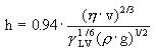
h = coating thickness, η = viscosity, γLV = liquid-vapour surface tension, ρ = density, g = gravity.

As it can be expected, the coating thickness is mainly defined by the withdrawal speed, by the solid content and the viscosity of the liquid. The withdrawal speed must be chosen such that the shear rates keep the system in the Newtonian regime, in such a case the Landau-Levich equation becomes really accurate. As shown by James and Strawbridge for an acid catalyzed silicate sol, thicknesses obtained experimentally fit very well to calculated values.
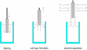
The interesting part of dip coating processes is that by choosing an appropriate viscosity the coating thickness can be varied with high precision from 20 nm up to 50 μm while maintaining high optical quality. The schematics of a dip coating process are shown in figure 1.
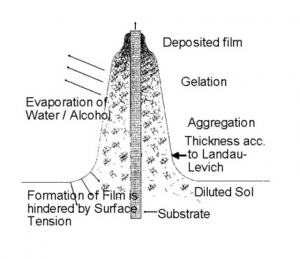
When reactive systems are chosen for coatings, as it is the case in sol-gel types of coating using alkoxides or pre-hydrolyzed systems – the socalled sols – the control of the atmosphere is indispensable. The atmosphere controls the evaporation of the solvent and the subsequent destabilization of the sols by solvent evaporation, leads to a gelation process and the formation of a transparent film due to the small particle size in the sols (nm range). This is schematically shown in figure 2.
In general, sol particles are stabilized by surface charges, and the stabilization condition follows the Stern’s potential consideration. According to Strn’s theory the gelation process can be explained by the approaching of the charged particle to distances below the repulsion potential. Then the repulsion is changed to an attraction leading to a very fast gelation. This takes place at the gelation point as indicated in figure 2.
The resulting gel then has to be densified by thermal treatment, and the densification temperature is depending on the composition. But due to the fact that gel particles are extremely small, the system shows a large excess energy and, in most cases, a remarkably reduced densification temperature compared to bulk-systems is observed.
However, it has to be taken into consideration that alkaline diffusion in conventional glasses like soda lime glasses starts at several hundred degrees centigrade and, as shown by Bange, alkaline ions diffuse into the coated layer during densification. In most cases, this is of no disadvantage, since the adhesion of these layers becomes perfect, but influences on the refractive index have to be taken into consideration for the calculations for optical systems.
Of course, this thickness calculation mostly corresponds to the value measured at the center of the lens. Ideally, to get a homogeneous thickness on the lens, a speed gradient should be applied, but only a few machines allow it. Yet, this is the best way to overcome the famous tear problem on bi-focal lenses along the segment.
Some machine manufacturers who cannot offer the gradient speed feature either recommend extremely slow speed leading to insufficient coating thickness to guarantee the scratch resistance, or extremely high-speed leading to potential cracking of the coating layer during the curing stage.
The best solution being to run those lenses at the nominal speed specified by the lacquer supplier followed with the maximum acceleration that the robot can deliver as this is increasing the centrifugal effect to expel the tear out of the lens. Anyway, with the spreading of freeform lenses in the market, the bi-focal lenses are likely to become just a piece of ophthalmic history.
Back to what is creating the chemical bonding of the lacquer to the lens. It is of course linked to the chemical composition of the lacquer which must contain a certain amount of epoxy groups to ensure the maximum adhesion to the lens substrate as can be seen in figure 3. It is clear that with this covalent bonding, an extremely strong adhesion level can be reached, making it difficult to remove the coating layer.
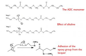
Fig. 3: Reactions occurring in the machine during the pre-curing of the hard coating.
Last but not least…
It is of prime importance to control temperature and Relative Humidity (RH) within the machine. However, because of the lower flash point of methanol and its high evaporation rate, methanol-based lacquers require a tank temperature around 10°C. Yet, when RH is set at 40%, condensation occurs when temperature difference with air gets higher than 6°C. This, in practice, requires that operators should work in a room where temperature is lower than 16°C, or that (what is generally the case), condensation occurs, reducing the pot life of this family of lacquers that was originally developed for fast drying
and high throughput.
Conclusions
It is clear that the outcome of a dip coating process is purely driven by physical and chemical parameters. When knowing this, there is no surprise with the result obtained from it. Machine manufacturers must understand that, from now on, actual and potential customers will no longer accept equipment which do not comply with the minimum requirements needed to ensure the maximum quality for their lens production.
Author
 Breton graduated with an engineering degree in Chemistry followed by a PhD in Organic Chemistry and a PostDoc in Polymer materials. He started his career in big US companies such as GE and Goodyear before entering the Optical sector back in 1999 with SDC Coatings. He successively worked with NGL and FISA before creating his own company named Chemoptics. This company later became HPMAT (High Performance MATerials) to reflect activities outside the Optical sector and a JV was created in Russia under the name of FBOptics but as can be expected, it is now ‘on hold’ until further notice!